• Just click on the image below for a PDF of the project details •
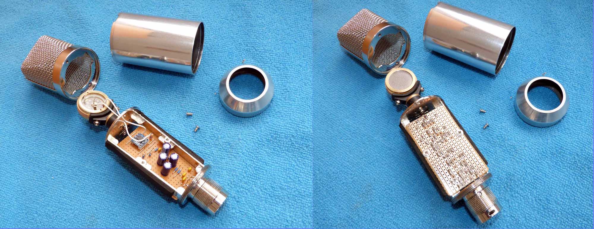
Alternatively, you may prefer to build a mic using a PCB rather than stripboard...
Hobby microphone builder Mic Scharf has developed a PCB for this version of the project,
which you can obtain from:
HERE
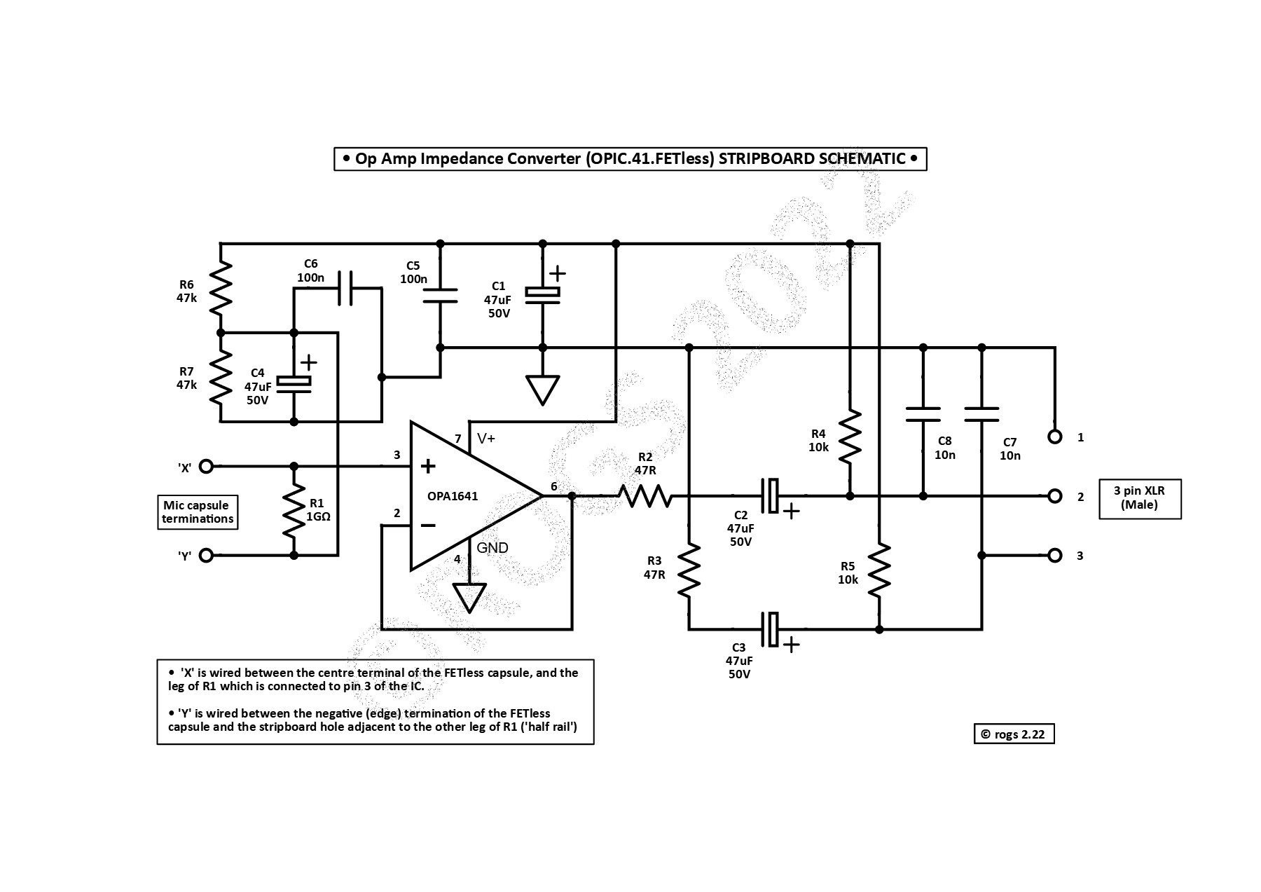
The schematic above shows the simple circuitry required to interface a 'FETless' electret microphone capsule (that is one without an internal FET) with a microphone pre-amplifier.
The preamplifier must have the capability to supply 48v phantom power to the circuitry.
This most simple application using the OPA1641 opamp only includes 2 resistors in the signal path - R1 and R2. This will help to minimise any noise generated by the circuitry, and should allow for microphone with a self noise level of only around 5dB (A-weighted) to be created.
As it is being used here with an electret capsule, there is no need to generate any polarisation voltage to bias the capsule.
The audio output is only fed - via C2 - to the 'hot' output (pin 2) of the XLR. The 'cold' output (pin 3) is passively balanced to ground - via R3 and C3 - to help maximise the system CMRR (Common Mode Rejection Ratio).